
Drawings, Models & Visualization

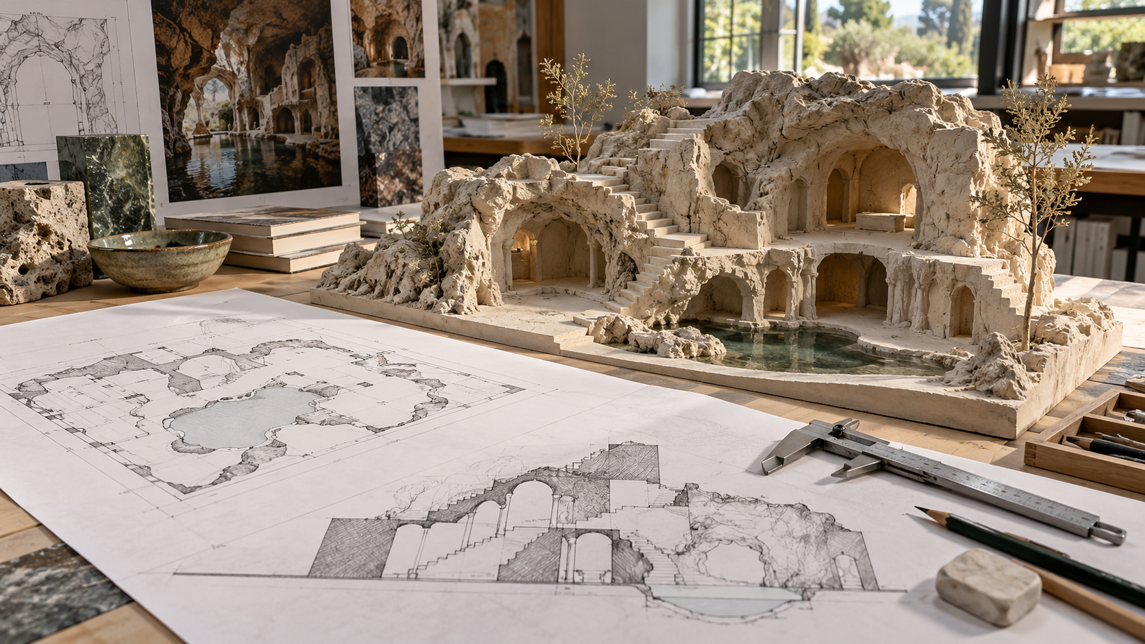
Illustration of a grotto model with architectural plans and sections

A rendering can make a grotto feel finished before its dimensions have been resolved. A rough section, by contrast, may reveal the one relationship that determines whether the concept works. Drawings, Models & Visualization explores how different representations answer different design questions. Plans organize movement, sections explain height, physical models reveal massing, and digital views help communicate atmosphere. None needs to do every job. Learn to choose a representation that suits the current decision, whether comparing entrances, coordinating hidden systems, or explaining the intended rock character. The collection also examines the limits of persuasive imagery: lenses, flattering light, and omitted equipment can make an unresolved proposal seem more complete than it is. Readers commissioning a grotto can learn what to request and how to interpret it; designers can consider clearer ways to connect visual studies with documented geometry. A useful presentation leaves room for questions while making the important relationships understandable. Its value lies in helping people reach informed decisions about the same proposed space, rather than simply producing an image that everyone finds attractive.

Plan drawing: Organizes horizontal relationships and circulation.
Section drawing: Reveals height, depth, and overhead form.
Elevation: Describes a face without perspective distortion.
Physical model: Makes masses and openings tangible.
Digital model: Supports repeatable views of defined geometry.
Rendering: Communicates appearance under chosen visual conditions.
Scale: Connects represented objects with intended dimensions.
Annotation: Explains information that an image cannot show alone.
Revision: Identifies which version a review concerns.
Purpose: Choose the representation for the decision being made.
Early sketches: Speed can matter more than polished detail.
Sections expose: Overhangs become clearer in vertical cuts.
Eye-level views: Visitor positions differ from aerial presentations.
Lens effects: Wide angles can exaggerate apparent room size.
Material studies: Texture images do not establish physical performance.
Lighting assumptions: Rendered atmosphere depends on chosen conditions.
Service omissions: Hidden equipment still occupies real space.
Model limits: Simplified geometry should be identified.
Comparative views: Matching camera positions make alternatives easier to judge.
Drawing coordination: Different representations should describe the same proposal.
Tracing paper: Explore alternatives over a stable base plan.
CAD tools: Maintain dimensions and organized drawing information.
Modeling software: Examine form through editable geometry.
Clay or foam: Make quick physical massing studies.
Scale figures: Communicate occupation and relative size.
View templates: Preserve camera positions between revisions.
Material boards: Pair visual references with actual samples.
Review markups: Record decisions directly against the relevant version.
File naming rules: Keep issued and working documents distinguishable.
Presentation checklists: Confirm the intended question is answered.
Representation bias: Every format emphasizes some relationships and conceals others.
Decision sequencing: Detail should follow the questions that need resolution.
Geometric consistency: Rendering changes should be reflected in coordinated drawings.
Model hierarchy: Broad forms can be tested before fine texture exists.
Photorealism limits: Visual credibility is not proof of constructability.
View selection: Include ordinary use positions alongside dramatic perspectives.
Review clarity: Separate approved decisions from unresolved options.
Version discipline: Outdated images can create conflicting expectations.
Physical comparison: A model can reveal relationships difficult to explain verbally.
Handoff quality: The next team needs usable information, not only attractive pictures.
Rough precision: A simple section can answer a complex spatial question.
Camera height: Lowering a viewpoint can transform perceived enclosure.
White models: Removing color can clarify massing.
Shadow studies: A small model can reveal surprising light relationships.
Hidden backs: A hero view may conceal an unresolved rear elevation.
Tiny people: Incorrect scale figures can mislead the viewer.
Cutaway views: Removing part of a model can explain concealed systems.
Revision trails: Earlier sketches reveal why the final arrangement changed.
Material ambiguity: The same rendered texture may suggest several construction systems.
Shared language: Clear drawings help specialists discuss the same geometry.
Q: Is a rendering a construction document?
A: Not by itself. It usually communicates appearance rather than the complete technical design.
Q: Which drawing best explains headroom?
A: A suitably placed section is especially useful.
Q: Why use a physical model?
A: It allows direct inspection of masses, openings, and relationships from several angles.
Q: Can a wide-angle rendering be misleading?
A: It can exaggerate apparent space if its viewpoint is not understood.
Q: Should alternatives use matching views?
A: Yes. Consistent viewpoints make differences easier to compare.
Q: When is detailed texture unnecessary?
A: During early questions about footprint, circulation, and enclosure.
Q: What should a presentation identify?
A: Version, scale where relevant, assumptions, and unresolved decisions.
Q: Can digital models omit service equipment?
A: They can, but that omission should not be mistaken for available space.
Q: Why retain earlier versions?
A: They document decisions and help prevent confusion about approved changes.
Q: What makes visualization useful?
A: It enables a specific design decision with clear, appropriately qualified information.